

 English
 Español
Home / News / Industry News / Elevator Guide Rail: Types, Standards, Installation & How to Choose the Right One
Industry News

Tel/wechat/whatsapp: +86-13812695057
E-mail: [email protected]
Content
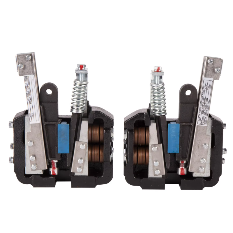
An elevator guide rail is a precision-machined steel structural component installed vertically within an elevator shaft to guide and constrain the movement of the elevator car and counterweight along a defined, controlled path. Guide rails are among the most fundamental components in any elevator system — they perform several critical functions simultaneously throughout the elevator's operating life. They keep the car and counterweight moving in a perfectly straight vertical line regardless of load distribution within the car, they resist the lateral forces generated during acceleration, deceleration, and passenger loading eccentricity, and most importantly, they provide the gripping surface against which the elevator's safety gear (progressive safety device or instantaneous safety gear) clamps in the event of an overspeed or free-fall condition to bring the car to a controlled stop.
Without properly specified, installed, and maintained guide rails, an elevator car would sway, vibrate, and potentially derail under normal operating conditions. The guide rail system is therefore not merely a structural convenience — it is a safety-critical component whose dimensional accuracy, surface finish, material properties, and installation alignment directly determine both the ride quality experienced by passengers and the reliability of the safety system in an emergency. Every major elevator safety standard in the world — EN 81-20 in Europe, ASME A17.1 in North America, GB 7588 in China, and their equivalents — contains detailed mandatory requirements for guide rail selection, installation, and inspection.
Elevator guide rails are also referred to as lift guide rails, car guide rails, counterweight guide rails, or T-type guide rails depending on context. The T-section profile — a flat web with a perpendicular blade (the guiding surface) — is by far the dominant cross-section in modern elevator installations worldwide, though hollow and other profile types exist for specific applications. Guide rails are manufactured in standard lengths — typically 3 meters or 5 meters — and are joined end-to-end with fishplates (splice brackets) to span the full height of the elevator shaft.
Elevator guide rails are classified by their cross-sectional profile, manufacturing method, and surface condition. Each type is suited to specific elevator categories, speed ranges, and load requirements.
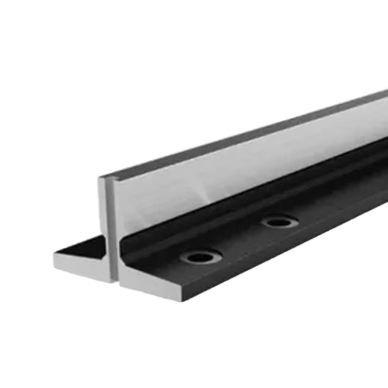
T-type solid guide rails are the universal standard for passenger and freight elevators operating across the full range of commercial and residential applications. The cross-section resembles an inverted T: a wide, flat base flange (the web) that is bolted to guide rail brackets fixed to the shaft wall, and a perpendicular blade that projects into the shaft and provides the three-sided guiding surface against which the elevator car's guide shoes or roller guides bear. The blade's three working surfaces — the front face and the two side faces at the base of the blade — are precision machined to tight dimensional tolerances and a smooth surface finish that minimizes friction and wear at the guide shoe contact and, critically, provides a consistent gripping surface for the safety gear. Solid T-type guide rails are manufactured as hot-rolled or cold-drawn steel sections and are available in a comprehensive range of standard sizes from small residential elevator rails (e.g., T45 or T50 sections) to large freight and high-speed elevator rails (T140, T160, T180, and above).
Hollow guide rails use a tubular or box-section profile rather than a solid T-section. The hollow construction reduces weight per meter compared to a solid rail of equivalent external dimensions, which is advantageous in applications where shaft wall loading must be minimized or where installation in lightweight building structures is required. Hollow guide rails are commonly used for hydraulic elevator counterweights, low-speed residential elevators, and platform lifts where the loads are lighter and the safety gear requirements are less demanding than for traction passenger elevators. Their guiding precision is generally lower than machined solid T-rails, and they are not typically suitable for elevator systems requiring progressive safety gear engagement because the hollow section cannot develop the clamping forces that a solid blade absorbs without permanent deformation.
Counterweight guide rails guide the elevator counterweight — a weighted frame that travels in the opposite direction to the car to balance the system and reduce motor load — along a separate set of rails in the shaft. In most installations, counterweight guide rails are smaller in cross-section than the car guide rails because the counterweight generates smaller eccentric loads and — in most jurisdictions — is not required to have a safety gear (though some standards, including EN 81-20 for certain configurations, mandate counterweight safety devices). Counterweight guide rails are typically specified one or two size grades below the car guide rails for the same installation, though in high-rise or high-speed elevators where counterweight safety gear is fitted, counterweight rail sizing follows the same methodology as car rail sizing.
The manufacturing process applied to the guide rail's working surfaces has a direct impact on dimensional accuracy, surface finish, and suitability for high-speed applications. Hot-rolled T-rails have a mill surface finish adequate for low-speed installations using sliding guide shoes with lubrication. Cold-drawn guide rails are produced by drawing the hot-rolled section through a die at room temperature, which improves dimensional accuracy, straightness, and surface finish substantially compared to hot-rolled. Machined guide rails undergo precision grinding or milling of the blade's three working surfaces after hot-rolling or cold-drawing, achieving the tight dimensional tolerances (typically ±0.05 mm on blade width and face flatness) and smooth surface finish (Ra ≤ 1.6 µm) required for high-speed elevators using roller guide assemblies, where even small surface irregularities translate directly into cabin vibration perceptible to passengers.
T-type elevator guide rails are designated by a size number that reflects the blade width in millimeters — the primary dimension that determines the guiding surface area and the section modulus available to resist bending loads. The full designation also includes the rail's unit weight (kg/m) and the specific standard it conforms to. Understanding these designations is essential for specifying compatible guide shoes, safety gear, and fishplates.
| Rail Designation | Blade Width (mm) | Blade Height (mm) | Base Width (mm) | Unit Weight (kg/m) | Typical Application |
| T45 | 45 | 45 | 82 | 8 | Residential, small goods lifts |
| T50 | 50 | 50 | 90 | 10.5 | Residential, light commercial |
| T70 | 70 | 65 | 115 | 16 | Standard commercial passenger |
| T89 | 89 | 62 | 127 | 22.3 | Commercial passenger, mid-rise |
| T114 | 114 | 89 | 152 | 36 | High-rise, high-speed, freight |
| T127 | 127 | 89 | 152 | 40 | Heavy freight, high-rise |
| T140 / T160 | 140–160 | 100–115 | 175–200 | 50–65 | Very high-rise, ultra-high-speed |
The dimensional designations above follow the predominant international practice, though slight variations exist between EN 81 (European), GB/T (Chinese), and ASME A17.1 (North American) standard series. When specifying or ordering guide rails for a project, always confirm that the rail dimensions conform to the specific standard edition applicable to your jurisdiction and elevator design code, and request dimensional certification from the manufacturer confirming compliance.
Elevator guide rails must meet defined material specifications to ensure adequate strength under normal guiding loads and, critically, under the high-impact loads imposed during safety gear engagement. The material properties most important to guide rail performance are yield strength, tensile strength, impact toughness, and internal soundness (freedom from inclusions and laminations that could cause brittle fracture under safety gear loading).
Guide rails are manufactured from structural carbon steels with yield strengths typically in the range of 235–355 MPa, equivalent to grades such as S235JR, S275JR, or S355JR under EN 10025, or ASTM A36/A572 under North American standards. For high-speed elevators and progressive safety gear applications, higher yield strength grades — S355 or equivalent — are specified to resist the concentrated bending stress at the safety gear engagement zone without permanent deformation that could prevent the car from being freed after an emergency stop. Chinese national standard GB/T 22562 specifies dedicated guide rail steel grades (e.g., QU type) with tighter requirements for surface finish, straightness, and mechanical properties than general structural steel standards, reflecting the critical safety function of guide rails in elevator systems.
Impact toughness — the material's ability to absorb energy during sudden loading without brittle fracture — is tested by Charpy V-notch impact testing at defined temperatures. Cold-temperature impact toughness is particularly important in guide rails for elevator installations in unheated shafts in cold climates, where the steel temperature may drop significantly below 0°C and the risk of brittle fracture under the instantaneous loading of safety gear engagement is elevated. Guide rail specifications for these environments should explicitly require Charpy impact certification at the lowest expected service temperature.
Guide rail sizing is a structural engineering calculation that must account for the forces imposed on the rails under all operating conditions, including normal operation, safety gear activation, and buffer engagement. The following parameters drive the sizing calculation.
Under normal operation, guide rails experience lateral forces from guide shoes or roller guides as the car accelerates, decelerates, and responds to eccentric load distribution within the car. These forces are relatively small compared to the forces imposed during safety gear engagement, which is the governing load case for guide rail sizing. When the safety gear activates, it grips the guide rail blade with a clamping force sufficient to decelerate the car from the governor trigger speed to rest within the distance limits specified by the safety standard. The resulting bending moment in the guide rail at the safety gear contact point — combined with the buckling load from the vertical component of the safety gear force — must be resisted by the rail section without exceeding allowable stress limits defined in EN 81-20 Annex G or equivalent standard appendices. This calculation requires knowledge of the car mass, rated load, safety gear type (instantaneous or progressive), governor trigger speed, guide bracket spacing, and the safety factor applied by the standard.
Guide rails are not continuously supported along their length — they are fixed to the shaft wall at discrete bracket positions, typically spaced 2.5 to 5 meters apart depending on shaft construction and rail size. The bracket spacing directly affects the bending moment the rail must resist under lateral loading: doubling the bracket spacing approximately quadruples the bending moment for the same lateral force. Tighter bracket spacing allows a smaller rail section to be used for the same load case, while wider spacing requires a heavier, stiffer rail. In concrete shafts with regular bracket fixing opportunities, 2.5–3 meter spacing is typical; in steel-framed shafts or where bracket positions are constrained by building structure, spacing up to 5 meters may be necessary with corresponding rail size increases. The bracket spacing used in the design must be confirmed during shaft survey and cannot be changed after rail sizing is finalized without recalculating rail section adequacy.
The type of safety gear fitted to the elevator — instantaneous (snap-action) or progressive (gradual braking) — has a major impact on guide rail loading. Instantaneous safety gears, used on elevators with rated speeds up to approximately 0.63 m/s, apply the full braking force almost instantaneously when triggered, generating very high impact loads on the guide rail at the engagement point. Progressive safety gears, used at higher speeds, apply braking force gradually through a spring and wedge mechanism, limiting peak deceleration and therefore peak rail stress. For the same car mass and speed, a progressive safety gear imposes lower peak forces on the guide rail than an instantaneous gear, which is reflected in the guide rail sizing calculation — progressive gear installations can often use a smaller rail section than an equivalent instantaneous gear installation at the same speed.
Elevator guide rails are subject to both product manufacturing standards — which govern dimensions, material properties, and surface finish — and elevator system safety standards — which govern how rails must be sized, installed, and maintained within a complete elevator installation. Both categories of standard must be satisfied simultaneously.
Correct installation of elevator guide rails is as important as correct specification. Misaligned, improperly jointed, or inadequately secured rails produce vibration, accelerated guide shoe wear, noise, and potentially unreliable safety gear engagement. These are the installation requirements that most directly affect elevator performance and safety.
Guide rails must be installed plumb — truly vertical — and parallel to each other within tight tolerances across the full shaft height. EN 81-20 specifies maximum permissible deviations from the theoretical centerline position: typically ±0.5 mm per meter of rail height locally (at any single bracket point) and a total accumulated deviation of no more than ±1.0 mm over any 5-meter section of rail. Deviation in the plane parallel to the car entrance (the x-direction, affecting door sill clearance) is generally held to tighter tolerances than deviation in the perpendicular plane (y-direction) because x-direction misalignment directly affects landing door sill gap consistency. In high-speed elevator installations, alignment tolerances are tighter still — some high-rise elevator manufacturers specify ±0.3 mm or better over 5 meters for installations above 4 m/s. Achieving these tolerances requires a combination of precision plumbing wire (piano wire or laser plumb lines) stretched from the top of the shaft to the pit, and adjustable rail bracket clips that allow fine lateral adjustment before final tightening.
Guide rail lengths are joined end-to-end using fishplates — pairs of steel plates bolted across each rail joint on the web and flanking the blade — that transfer loads across the joint and maintain dimensional continuity between adjacent rail sections. The joint between rail lengths must meet strict requirements: the faces of abutting rail ends must be flush within 0.05 mm in the guiding plane, with no step, gap, or offset that could be felt by guide shoes or roller guides and transmitted as vibration to the cab. Prior to assembly, the mating rail ends are checked for flatness and any high spots are dressed down with a file or grinding stone. Fishplates are tensioned to the torque specified by the rail manufacturer or elevator contractor — typically 80–120 N·m for M16 bolts — using a calibrated torque wrench, and checked for correct torque during commissioning inspection. In seismically active regions, special fishplate designs that allow limited controlled rail movement during earthquake loading — preventing catastrophic rail fracture from seismic lateral forces — are required by local codes.
Guide rail brackets transmit all loads from the guide rails to the building structure, and their fixing design must account for the full range of static and dynamic loads including safety gear activation. Brackets are typically fabricated from structural steel plate and are either cast into the concrete shaft wall during construction (cast-in channel systems), drilled and anchored into hardened concrete (chemical anchor or expansion anchor systems), or bolted to pre-installed steelwork in steel-framed shafts. The fixing capacity of brackets and their anchors must be verified by calculation to exceed the design loads with the safety factors specified in the applicable standard — typically a minimum safety factor of 2 against the calculated safety gear loads. For concrete anchor fixing, anchor pull-out and shear capacity must be calculated using the concrete strength of the specific shaft construction, not generic tabulated values, since anchor capacity varies significantly with concrete grade and edge distance.
Proper lubrication of elevator guide rails extends the service life of both the rails and the guide shoes, reduces energy consumption from friction, and contributes to quiet, smooth ride quality. Maintenance inspection of guide rails ensures that dimensional accuracy and structural integrity are preserved throughout the elevator's operating life.
Sliding guide shoes — the traditional guide shoe type using a replaceable plastic or bronze liner that slides directly on the rail blade — require continuous lubrication with a light mineral oil or purpose-formulated elevator rail lubricant applied by an automatic rail oiler mounted on the car sling. The oiler distributes a controlled quantity of lubricant to the rail surface as the car passes, maintaining a thin film at the shoe-rail interface that reduces friction and prevents adhesive wear. Over-lubrication wastes lubricant and creates an oil mist contamination problem in the shaft; under-lubrication allows metal-to-metal contact between the shoe liner and rail surface, causing accelerated liner wear, increased friction heat, and potentially audible squealing. Automatic oilers should be inspected and refilled at intervals defined by the maintenance schedule — typically every 3–6 months depending on elevator utilization — and adjusted to deliver the minimum lubricant quantity that maintains a visible film on the rail surface.
Roller guide assemblies — used on high-speed elevators where the smoothness and low friction of rolling contact is required — run on the rail surface without oil lubrication. The polyurethane or nylon roller tread material is self-lubricating and designed for dry running. Oil contamination of roller guide rails from adjacent oiled sliding shoes or from oil migration in the shaft can actually degrade roller guide performance by causing roller skidding rather than rolling, so oil contamination of roller guide rail sections must be avoided and cleaned promptly if it occurs.
Guide rails are safety-critical components, and the consequences of substandard material or dimensional non-conformance in service can be catastrophic. Thorough quality verification before acceptance of a guide rail delivery is not optional — it is a professional and regulatory obligation for elevator installers and maintenance companies.
Tel/wechat/whatsapp: +86-13812695057
E-mail: [email protected]
Add: Building 7, No. 268, Chang 'an Road, Bache Sub-district, Dong Taihu Ecological Tourist Resort (Taihu New Town), Wujiang District, Suzhou City, Jiangsu Province, China