
 English
 Español
Home / News / Industry News / Elevator Pulley: Types, Groove Profiles, Inspection Guide & Replacement Tips
Industry News
Tel/wechat/whatsapp: +86-13812695057
E-mail: [email protected]
Content
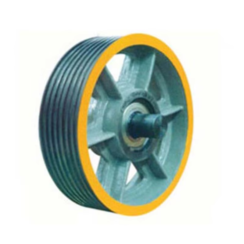
An elevator pulley — also called a sheave in technical terminology — is a grooved wheel over which elevator ropes or steel belts pass to transmit motion and support the load of the elevator car and counterweight. Every traction elevator system depends on pulleys to redirect rope travel, multiply mechanical advantage, and transfer drive force from the traction machine to the car. Without properly designed, manufactured, and maintained elevator sheaves, the ropes would wear rapidly, the traction machine would be unable to move the car efficiently, and the risk of rope slippage or mechanical failure would increase dramatically.
The terms "elevator pulley" and "elevator sheave" are used interchangeably in the industry, though technically a sheave specifically refers to a grooved pulley used with rope or cable. In elevator engineering, sheave refers to the grooved wheel itself, while pulley sometimes refers to the complete assembly including the shaft, bearings, and housing. Regardless of terminology, these components sit at the heart of every traction elevator's mechanical system, and their geometry, material, groove profile, and condition directly determine elevator performance, rope life, and passenger safety.
This article covers how elevator pulleys work, the different types used in elevator systems, the materials and manufacturing standards involved, how to inspect and maintain them, and what to look for when specifying replacement sheaves. Whether you are an elevator technician, a building facilities manager, or an engineer designing a new installation, understanding elevator pulleys in detail is fundamental to keeping elevator systems running safely and efficiently.
In a traction elevator, the drive machine — an electric motor connected to a gearbox or a gearless direct-drive motor — rotates a traction sheave. Steel wire ropes or coated steel belts are draped over the traction sheave, with the elevator car suspended on one side and the counterweight on the other. The friction between the rope and the grooves of the traction sheave is what drives the car up and down — the machine doesn't pull the rope like a winch; it grips it through traction. This fundamental distinction is why groove profile, rope-to-sheave diameter ratio, and groove material all have such a direct impact on system performance.
Beyond the main traction sheave, a complete elevator system uses several additional pulleys. Deflector sheaves redirect the rope path from the traction machine to the car or counterweight when the machine is not positioned directly above the hoistway. Idler sheaves maintain rope tension and correct alignment through the system. In roped hydraulic elevators and some traction systems, multiple sheaves are arranged in a pulley block configuration to achieve mechanical advantage — the 2:1 and 4:1 roping arrangements used in many elevator systems require deflector and idler sheaves to complete the rope path. Each sheave in the system contributes to rope bending fatigue, so the number of sheaves, their diameters, and the bending angles all affect the service life of the ropes.
A complete elevator installation uses several distinct types of sheaves, each designed for a specific function in the rope system. Understanding what each type does and where it is located helps in diagnosing problems and specifying correct replacements.
The traction sheave is the primary drive element of the elevator system. It is mounted directly on the output shaft of the traction machine — either through a gearbox or directly on a gearless motor shaft — and its rotation drives the elevator car and counterweight through rope friction. Traction sheaves are the most heavily loaded pulleys in the system, subject to both the full rope tension and the bending fatigue from ropes continuously flexing over the sheave surface. Their groove profile must be precisely matched to the rope diameter, and the groove material must provide adequate traction without causing excessive rope wear. Traction sheave diameters range from approximately 320 mm on small residential elevators to over 800 mm on high-speed commercial systems.
A deflector sheave is used to redirect the rope path from the traction machine to the correct vertical alignment over the car or counterweight when the machine is not positioned directly above the hoistway centerline. In machine-room-less (MRL) elevator installations, where the drive machine is mounted at the top of the hoistway rather than in a dedicated machine room, deflector sheaves are particularly important for establishing the correct rope geometry. Deflector sheaves are also used in overhead machine room installations where the machine is offset from the hoistway center. They carry significant rope tension loads and must be sized and supported to handle these forces without deflection or vibration.
In 2:1 roping configurations — where the rope travels from a fixed anchor point, down around a sheave on the car frame, back up to a deflector or overhead sheave, and down to the counterweight — the car sheave and counterweight sheave are mounted on the car frame and counterweight frame respectively. These sheaves allow the car and counterweight to travel at half the rope speed of a 1:1 system, which reduces the required rope speed and allows a smaller traction machine to move the same load. Car sheaves must be designed with adequate rope clearance within the car frame structure, and their bearings must handle the full suspended load of the car plus rated load divided between the rope falls.
Overhead sheaves are fixed pulleys mounted at the top of the hoistway or in the machine room overhead structure that redirect ropes between the traction sheave and the car or counterweight sheave in multi-wrap or complex roping configurations. In 4:1 roping systems used in some low-speed, high-capacity freight elevators, multiple overhead sheaves complete the pulley block arrangement. These sheaves are typically smaller in diameter than the traction sheave and are designed primarily to redirect rope path rather than to provide traction.
In tall buildings where rope weight becomes significant — typically in buildings over 30 meters served height — compensation ropes or chains are hung below the car and counterweight to balance the weight of the hoisting ropes as the car travels. A compensation sheave is mounted in the elevator pit to guide the compensation ropes and maintain appropriate tension. Compensation sheaves are tensioned by gravity and must be free to move vertically within limits to accommodate rope elongation and dynamic rope movement during operation.
The groove profile of an elevator pulley is one of the most technically critical aspects of elevator design, directly affecting both traction performance and the rate of rope wear. Three principal groove profiles are used in elevator sheaves, each representing a different trade-off between traction, rope pressure, and rope fatigue life.
A round groove has a circular cross-section with a radius slightly larger than the rope radius — typically the groove radius is 0.53–0.55 times the rope diameter. The rope contacts the groove over a large arc (approximately 120–150°), distributing the contact pressure evenly over a wide area. This low contact pressure produces minimal rope deformation and maximum rope fatigue life, making round groove sheaves the preferred choice for all deflector sheaves, car sheaves, and overhead sheaves where traction is not required. The limitation of round grooves on traction sheaves is that they provide lower traction (friction) than undercut grooves, which can be insufficient for systems with low counterweight ratios or high acceleration requirements.
An undercut groove combines a V-shape with a small radius undercut at the bottom. The angled sides of the groove squeeze the rope, generating a wedging effect that significantly increases the normal force between rope and groove — and therefore increases the available traction — compared to a round groove under the same rope tension. The traction coefficient achievable with an undercut groove is typically 50–80% higher than with a round groove of equivalent groove angle, which is why undercut grooves are the standard profile for traction sheaves in most modern elevator installations. The trade-off is higher contact pressure on the rope wires at the groove edges, which accelerates rope wear and reduces rope fatigue life. Undercut groove angles typically range from 90° to 105°, with deeper undercuts providing higher traction at the cost of faster rope degradation.
A full V-groove without undercut generates maximum traction through extreme wedging action, but at the cost of very high contact pressures that cause rapid rope wear. Full V-grooves are rarely used in modern passenger elevator traction sheaves but may be found in older installations or in some freight and service elevator applications. The high rope-to-groove contact pressure in a V-groove also causes rapid groove wear itself, requiring more frequent traction sheave replacement compared to undercut groove designs. Where full V-grooves are encountered in existing installations, their condition should be carefully assessed during maintenance inspections.
Elevator sheaves are manufactured from materials selected to provide the correct combination of hardness, toughness, machinability, and wear resistance for their role in the system. The table below summarizes the main materials used and their characteristics:
| Material | Hardness Range | Primary Use | Key Characteristic |
| Gray Cast Iron (GG25, GG30) | 180–240 HB | Deflector, overhead sheaves | Good machinability, vibration damping, low cost |
| Ductile Iron (SG Iron) | 200–280 HB | Traction sheaves, car sheaves | Higher strength and toughness than gray iron |
| Cast Steel | 160–220 HB | Heavy-duty traction sheaves | High load capacity, can be heat treated |
| Forged Steel | 200–300 HB | High-speed, gearless traction sheaves | Highest strength, excellent fatigue resistance |
| Polyurethane-Lined Sheave | Shore A 85–95 | Flat belt (SUS/aramid) systems | Reduces belt wear, quieter operation |
Elevator sheaves must comply with relevant safety standards including EN 81-20 and EN 81-50 in Europe, ASME A17.1 in North America, and GB 7588 in China. These standards specify minimum sheave-to-rope diameter ratios (typically D/d ≥ 40 for traction sheaves where D is the sheave pitch diameter and d is the rope diameter), groove profile tolerances, material mechanical property requirements, and inspection criteria. Compliance with these standards is mandatory for elevator type approval and is verified during both manufacturing and periodic safety inspections.
The ratio of the sheave pitch diameter (D) to the rope diameter (d) — universally written as D/d — is one of the most important parameters in elevator rope and sheave system design. Every time a rope bends over a sheave, the outer wires of the rope are stretched in tension while the inner wires are compressed. The smaller the sheave relative to the rope, the more severe this bending stress, and the faster the rope accumulates fatigue damage. A D/d ratio of 40:1 — the minimum typically mandated by elevator safety standards for traction sheaves — means that for a 13 mm rope, the minimum sheave pitch diameter is 520 mm.
Using larger D/d ratios significantly extends rope life. Research and field data consistently show that increasing D/d from 40 to 60 can more than double rope fatigue life under equivalent loading. High-speed, high-cycle elevator systems — such as those in tall commercial buildings making hundreds of trips per day — often specify D/d ratios of 60–80 or higher to achieve acceptable rope service lives between replacements. The D/d ratio must be maintained for all sheaves in the system, not just the traction sheave, because rope bending fatigue is cumulative across every sheave the rope contacts during each trip cycle. Deflector sheaves and overhead sheaves are sometimes specified with smaller diameters than the traction sheave, but their contribution to rope fatigue must be accounted for in the overall rope life calculation.
Regular inspection of elevator sheaves is a mandatory element of elevator maintenance under all major safety standards. Sheave inspection serves two purposes: identifying worn or damaged sheaves before they cause rope damage or system failure, and verifying that the sheave system continues to provide adequate traction and rope life. The following inspection items should be included in every periodic elevator maintenance visit:
Deciding when to replace an elevator pulley rather than continuing to operate it or re-machining the grooves is a judgment that must balance safety, rope life, and maintenance cost. The following conditions require sheave replacement or groove re-machining and should be treated as mandatory action items when identified during inspection:
Machine-room-less (MRL) elevator technology, which became the dominant installation type for low-to-mid-rise buildings from the late 1990s onwards, introduced new challenges and configurations for elevator sheave systems. In MRL installations, the traction machine is mounted within the hoistway — typically at the top — and the rope geometry must be established using deflector sheaves positioned within the confined space of the hoistway structure. This places much greater demands on sheave positioning accuracy, structural support design, and maintenance access planning than conventional machine room installations. MRL deflector sheaves are often integrated into the machine bedplate assembly or mounted on dedicated steel brackets welded or bolted to the hoistway structure.
High-speed elevators serving tall buildings — those traveling at 4 m/s and above — impose severe demands on traction sheave performance. At high speeds, rope vibration, aerodynamic effects, and the dynamic impact forces at rope-sheave entry and exit points all increase substantially. High-speed traction sheaves are invariably forged steel or high-strength ductile iron, precision balanced to minimize vibration, fitted with high-precision bearings, and designed with carefully optimized groove profiles that minimize rope fatigue while maintaining adequate traction. The emergence of flat coated steel belt systems (such as Schindler's Multibelt and Otis' Gen2) for speeds up to 4 m/s introduced polyurethane-lined sheaves as an alternative to grooved iron sheaves, providing quieter operation and longer belt service life in mid-rise applications while simplifying sheave manufacturing compared to precision-grooved traction sheaves.


Tel/wechat/whatsapp: +86-13812695057
E-mail: [email protected]
Add: Building 7, No. 268, Chang 'an Road, Bache Sub-district, Dong Taihu Ecological Tourist Resort (Taihu New Town), Wujiang District, Suzhou City, Jiangsu Province, China


